In the world of electronics, moisture is a silent killer . It seeps into packages, creeps along traces, and—when combined with ionic contamination and electrical bias—triggers catastrophic failure mechanisms like corrosion and electrochemical dendrite growth. To uncover these latent weaknesses before products reach customers, engineers rely on one of the oldest yet most trusted environmental stress tests: Temperature, Humidity, and Bias (THB) testing.
Operating at the iconic 85°C / 85% relative humidity condition with continuous electrical bias, THB simulates years of tropical or high-humidity field exposure in a controlled laboratory setting. While newer tests like HAST (Highly Accelerated Stress Test) offer faster results, THB remains a gold standard for long-term reliability validation , especially in automotive, medical, and industrial applications where failure is not an option.
Temperature Humidity and Bias Testing (THB): The Complete Guide to Long-Term Moisture Reliability
While newer, faster tests like HAST have gained popularity, Temperature, Humidity, and Bias (THB) testing remains a cornerstone of electronic reliability validation. Its 85°C/85% RH condition provides a field-relevant, reproducible, and highly correlated stress environment that continues to expose critical weaknesses in materials, design, and manufacturing processes.
This comprehensive guide explores the principles, standards, failure modes, equipment, and best practices of THB testing—essential knowledge for semiconductor manufacturers, PCB designers, quality assurance teams, and reliability engineers.
What Is THB (Temperature, Humidity, and Bias) Testing?
THB testing is an accelerated environmental stress test that evaluates the long-term reliability of electronic components and assemblies under sustained exposure to:
– High temperature: 85°C
– High humidity: 85% relative humidity (RH)
– Continuous electrical bias: Typically at maximum rated voltage
The test is typically run for 1,000 hours (≈42 days), though durations of 500, 2,000, or even 3,000 hours are used for high-reliability applications.
THB is formally defined in key standards:
– JEDEC JESD22-A101 (Semiconductors)
– IEC 60068-2-60 (International)
– IPC-TM-650 Method 2.6.3 (PCBs)
Why 85°C / 85% RH?
This condition was chosen because:
– It represents a worst-case but realistic environment (e.g., tropical climates, engine compartments)
– It’s below the boiling point of water, avoiding phase-change complications
– It provides sufficient acceleration without inducing non-field-relevant failures
– It’s reproducible across global test labs
How THB Works: The Physics of Moisture-Induced Failure
Moisture Ingress Pathways
Under THB conditions, moisture penetrates devices through:
– Diffusion through mold compound or conformal coating
– Capillary action along leads, vias, or delamination paths
– Micro-cracks in packaging or solder mask
Key Failure Mechanisms Activated by THB
1. Electrochemical Migration (Dendrite Growth)
When moisture, ionic contaminants (e.g., Cl⁻, Na⁺ from flux residue), and electrical bias coexist, metal ions dissolve and migrate, forming conductive dendrites between adjacent traces. This leads to:
– Leakage current increase
– Intermittent shorts
– Catastrophic hard shorts
2. Corrosion of Metallization
Aluminum bond wires, copper traces, and nickel underplating corrode in humid, ionic environments, causing:
– Open circuits
– Increased resistance
– Parameter drift
3. Package Delamination
Moisture absorption causes swelling in mold compound, breaking adhesion between:
– Die and paddle
– Leadframe and encapsulant
– Layers in multi-chip modules
4. Dielectric Breakdown
Moisture reduces surface insulation resistance (SIR), enabling current leakage across supposedly isolated nodes—especially in high-impedance analog or RF circuits.
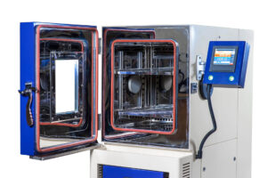
THB Test Setup & Equipment
THB Chamber Requirements
- Temperature control: ±2°C uniformity at 85°C
- Humidity control: ±3% RH at 85% RH
- Air circulation: Gentle fan to prevent stagnant zones
- Electrical feedthroughs: Hermetic, high-temp connectors for bias
- Water purity: Deionized water to prevent mineral deposits
Test Board Design
Devices are mounted on dedicated THB test boards featuring:
– Interdigitated comb patterns (to detect dendrites)
– Gold-plated traces (resistant to corrosion)
– Proper spacing (e.g., 0.3 mm for fine-pitch evaluation)
– Ground planes and guard rings to reduce noise
> 💡 Best Practice : Use test boards that mimic your actual product layout—generic boards may miss real-world failure modes.
Bias Configuration
- Voltage: Max rated VCC or datasheet-specified stress voltage
- Polarity: AC or DC (DC is standard)
- Monitoring: Optional real-time leakage current measurement
Industry Standards & Test Conditions
JEDEC JESD22-A101: Semiconductor THB
Defines:
– Condition A: 85°C / 85% RH / 1,000 hours / biased
– Condition B: 85°C / 85% RH / 500 hours / unbiased (rare)
Requires post-test electrical verification and failure analysis.
AEC-Q100/101: Automotive Qualification
- Grade 0/1 (150°C ambient): 1,000h THB or 96h HAST
- Grade 2/3 (125°C/85°C ambient): 1,000h THB or 48–96h uHAST
THB remains acceptable, though HAST is increasingly preferred for speed.
IEC & IPC Standards
- IEC 60068-2-60: International THB test method
- IPC-TM-650 2.6.3: THB for printed wiring assemblies
- IEC 60601-1: Requires THB-like validation for medical devices
MIL-STD-883 (Method 1004.2)
References THB for microcircuit reliability, though many military programs now accept HAST.
Applications by Industry
Automotive Electronics
Every engine control unit (ECU), infotainment system, and ADAS sensor must survive high under-hood humidity. THB validates:
– Conformal coating integrity
– Solder mask adhesion
– Connector seal reliability
Medical Devices
Implantables (e.g., pacemakers) and external monitors undergo THB to ensure decades of operation in body-temperature, high-humidity environments. A single corrosion failure could be life-threatening.
Industrial & Aerospace
PLCs, motor drives, avionics, and satellite payloads use THB to qualify for tropical, marine, or high-altitude deployments where condensation is common.
Consumer Electronics
While often replaced by HAST, THB is still used for:
– High-end smartphones (IP68 validation)
– Outdoor IoT sensors
– Wearables exposed to sweat and rain
THB vs. Other Humidity Tests
THB vs. HAST (Highly Accelerated Stress Test)
| Parameter | THB | HAST |
|---|---|---|
| Temperature | 85°C | 110–130°C |
| Humidity | 85% RH | ~100% RH (pressurized steam) |
| Pressure | Atmospheric | Elevated (2–3 atm) |
| Duration | 1,000+ hours | 96–200 hours |
| Acceleration | 1x (baseline) | 3–10x |
| Failure Relevance | High (field-correlated) | Moderate (risk of over-stress) |
THB vs. uHAST (Unbiased HAST)
uHAST removes electrical bias, focusing only on material integrity. THB is superior for detecting bias-dependent failures like dendrites.
THB vs. PCT (Pressure Cooker Test)
PCT (121°C, 100% RH, 2 atm, no bias) is a passive test for package integrity. THB is active and better for circuit-level reliability.
Common THB Failure Modes & Root Causes
1. Dendritic Short Circuits
Symptoms: Sudden drop in insulation resistance, functional failure
Root Cause: Ionic contamination + moisture + bias
Prevention: No-clean flux validation, thorough cleaning, wider trace spacing
2. Bond Wire Corrosion
Symptoms: Open circuit, increased series resistance
Root Cause: Moisture ingress through mold compound cracks
Prevention: High-quality mold compound, hermetic sealing where possible
3. Delamination at Die Attach
Symptoms: Thermal runaway, parameter drift
Root Cause: Poor adhesion, moisture-induced swelling
Prevention: Optimized curing process, low-moisture-absorption adhesives
4. Solder Mask Lifting
Symptoms: Corrosion on exposed copper
Root Cause: Low adhesion, thermal stress during reflow
Prevention: Plasma treatment, high-Tg solder mask
Post-THB Analysis & Inspection
Electrical Verification
- Functional test
- Parametric test (leakage current, IDDQ, gain)
- Insulation Resistance (IR) or Surface Insulation Resistance (SIR) measurement
Physical Failure Analysis
- Optical Microscopy: Visual dendrites or corrosion
- SEM/EDS: Elemental analysis of contaminants
- Acoustic Microscopy (SAT): Detect internal delamination
- Ion Chromatography: Identify specific ionic residues (Cl⁻, Br⁻, etc.)
Best Practices for Effective THB Testing
1. Control Ionic Contamination
Clean all PCBs post-assembly using validated processes. Residual flux is the #1 cause of THB failure. Use ROSE testing or ion chromatography to verify cleanliness.
2. Use Realistic Test Boards
Avoid generic comb patterns. Include actual component spacing, power planes, and signal layers from your product.
3. Monitor During Test (Optional but Powerful)
Install real-time leakage current monitoring to catch intermittent failures that might recover after power-off.
4. Correlate with Field Data
If THB-passed units fail in humid climates, your test may be insufficient. Adjust duration or add bias cycling.
5. Combine with Other Tests
Run THB after thermal cycling to simulate real-world combined stresses.
Limitations & Pitfalls of THB
Pitfall 1: False Failures from Poor Cleaning
A dirty board will fail THB regardless of design quality. Always validate your cleaning process first.
Pitfall 2: Over-Reliance on Pass/Fail
Measure degradation trends (e.g., leakage current vs. time), not just final pass/fail.
Pitfall 3: Ignoring Bias Configuration
Applying bias only to VCC/GND misses failures in signal lines. Bias all critical nets.
When THB May Not Be Sufficient
- For products in >85°C environments (use HTSL or power temperature cycling)
- For rapid development cycles (use HAST for faster feedback)
- For hermetically sealed devices (use fine leak testing instead)
Future Trends in THB Testing
1. Dynamic THB with Real Workloads
Future systems will run actual firmware during THB—simulating real switching activity under humidity stress.
2. In-Situ Monitoring & AI Analytics
Sensors embedded in test boards will stream leakage, temperature, and humidity data to cloud platforms, where AI predicts failure before it occurs.
3. THB for Advanced Materials
As halogen-free, bio-based, and ultra-thin PCBs emerge, THB protocols will adapt to their unique moisture absorption profiles.
4. Standardization of uTHB
Unbiased THB (uTHB) may gain traction for passive components, similar to uHAST.
For industries where safety, longevity, and trust are non-negotiable—automotive, medical, aerospace—THB is more than a test; it’s a promise. By rigorously applying THB with attention to contamination control, test board design, and failure analysis, engineers ensure that their products won’t just survive the lab—but thrive in the real world, no matter how humid.
Frequently Asked Questions (FAQ)
What is THB testing?
THB (Temperature, Humidity, and Bias) testing is a reliability stress test that exposes electronic components to 85°C temperature, 85% relative humidity, and continuous electrical bias for 1,000+ hours to accelerate moisture-related failures like corrosion and electrochemical migration.
What is the standard condition for THB testing?
The standard THB condition is 85°C temperature, 85% relative humidity (RH), and continuous DC bias at rated voltage, typically for 1,000 hours as defined in JEDEC JESD22-A101 and IEC 60068-2-60.
How is THB different from HAST?
THB uses 85°C/85% RH at ambient pressure and takes 1,000+ hours. HAST uses higher temperature (110–130°C), pressurized steam, and achieves similar stress in 96–200 hours—making HAST 3–5x faster but more aggressive.
Which components require THB testing?
Plastic-encapsulated ICs, PCB assemblies, connectors, and passive components used in automotive, medical, industrial, and consumer electronics often require THB testing per standards like AEC-Q100, IEC 60601, and IPC-TM-650.
Can THB testing be skipped if HAST is performed?
In many modern applications, HAST can substitute for THB due to its acceleration. However, some legacy specifications, military standards, or customer requirements still mandate THB. Always verify contractual obligations before replacing THB with HAST.